THERMAL ENERGY STORAGE
Reducing energy costs, one Preload tank at a time
In line with Preload’s tradition of designing and building sustainable and maintenance-free prestressed concrete tanks, Preload thermal energy storage (TES) tanks serve as vital components in highly efficient, long-lasting centralized cooling systems and data centers.
Preload TES tanks provide universities, hospitals, and government facilities the capability to realize hundreds of thousands of dollars in savings on energy costs while increasing sustainability and overall efficiency, and protect operations at critical facilities.
TES has a variety of other applications including turbine inlet cooling (TIC) at power generation facilities, emergency cooling for data centers and server farms, and dual purposing for fire protection water storage as a secondary use.


Background
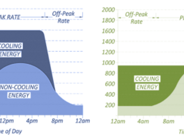
How thermal energy storage (TES) works
Thermal energy in the form of chilled water or heated water is produced during the off-peak times of less electrical demand. This chilled or heated water is collected in a thermal energy storage tank, and is then withdrawn and distributed to the facility during the peak heating or cooling periods. This technique is known as “load shifting.”
Load shifting is beneficial in two ways:
- It allows the chilling facility to cut costs on energy use by avoiding peak power prices, and
- It increases the efficiency of the system by running at night when temperatures are cooler.
Although the TES energy-saving technology has been available for decades, it has never before seen the far-reaching potential for application that it does now.
THE CASE FOR THERMAL ENERGY STORAGE
Thermal energy storage (TES), with its load-shifting operation technique, is a proven energy-saving technology that cost-effectively regulates plant load requirements. Large-scale developers are increasingly aware of the significant returns from rate off-setting, and reduced capital costs provided by thermal energy storage (TES).
Take advantage of rate offsets – If a new power plant is an infrastructure component of a large-scale development that integrates load regulation (shifting), the power plant has the ability scale back, thus reducing not only its construction and maintenance costs, but also minimizing the overall carbon footprint. In many cases, power providers offer incentives for facilities that utilize TES. These offsets are significant enough that the majority of new TES projects pay themselves off within 5 years.
Minimize capital costs – In addition to savings from rate offsets, adding TES can also reduce initial costs by using chillers more efficiently.
- New chiller plant projects can benefit from TES because it reduces the peak load requirement, thus fewer or smaller chillers are required.
- For chiller plant expansion projects, TES can be integrated into the existing infrastructure seamlessly to enhance efficiency by allowing for useful generation during times when the plant would otherwise be dormant.
Preload offers value assessments including capital planning budget estimates, plant optimization, and capital return period based on project-specific analysis.


STORING CHILLED WATER
Storing chilled water and keeping it chilled
The key to maintaining the temperature of the chilled water over long periods of time is to minimize heat transfer with warmer surroundings. Any heat transferred to the chilled water increases the temperature and releases some of the stored energy. Although Preload carefully designs an insulation system to minimize ambient heat gain from the outside air, most significant potential for heat gain actually occurs inside the tank. We install diffusers inside the tank to keep warm water from invading the cold water at the bottom of the tank.
Eliminating turbulence and maintaining the thermocline – As a part of a closed loop system, a TES tank also stores warm water that is returned from the heat exchanger (air conditioning unit). Warm and chilled water enter and exit the tank through diffusers located at the top and bottom of the tank, respectively. These diffusers are designed to eliminate turbulence and provide a stable, sharply defined transition layer, or “thermocline,” which allows for the natural stratification of warm water at the top of the tank and chilled water at the bottom.
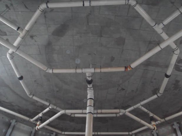
DIFFUSER DESIGNS
Diffuser piping arrangements
The diffuser piping is arranged in such a way that it “spreads” flow equally over a large area in order to minimize mixing. There are a number of ways to accomplish laminar flow within the tank and Preload offers unmatched experience with a variety of arrangement options to suit projects of all types.
Octagons for typical applications – Most TES systems utilize an octagonal arrangement. This type of system is perfect for larger-volume applications, such as district and turbine inlet cooling (TIC). As the name suggests, piping in this system is constructed with a number of concentric octagonal “rings,” each having evenly spaced inlet slots which distribute flow. For higher-flow applications, additional rings may be added to ensure adequate distribution. By adding more rings, the initial flow is split several times, which reduces the velocity through each pipe slot.
“H” pipe for smaller applications – For such smaller applications as emergency cooling for data centers, an “H” configuration is optimal. In this case, the smaller tank diameters often associated with emergency cooling limit the number of rings that can be constructed practically. Also, since flows tend to be higher for these applications, the straight pipe sections cover more plan area than a ring configuration might allow.
